
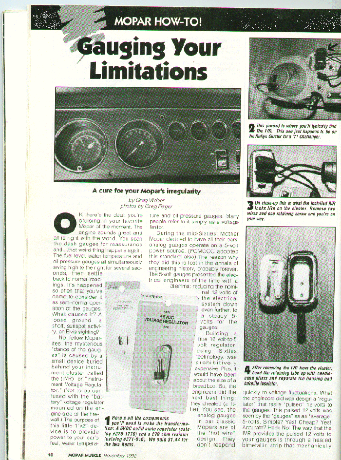
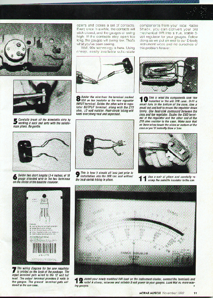
Moparts Tech Archive
Elec Topics
Instrument voltage reducer question...
Guys,
Thanks in advance.
73 RR uses a voltage reducer that drops the 12v down to 5v to run the instruments.
I have two reducers. Neither one appears to work.
Do they need a load on them before you can detect the 5v output?
I bought an Echlin voltage reducer that works 12v down to 6v. I imagine that will work but will I encounter the same problem with not having a load on the reducer?
Make sense?
Jim
The factory instrument voltage regulator works much like a turn signal flasher. The current flowing through it heats up a bimetal strip which breaks the circuit, resets and repeats the process. It must have a load to function.
The factory recommended test for the IVR is to turn the ignition switch on and stare at one of the gauges. The slight fluctuation of the needle as the circuit breaks means the IVR is working.
Dont forget the body must be grounded for the winding to heat up the bimetal strip !
Jim 440
I made an electronic regulator from parts at Radio Shack. The E-body ralley dash uses a regulator with wires. The home made one has a rock steady 5.0 Volts and looks like this:
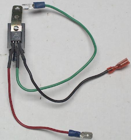
I got the info from the Aug 2000 issue of Mopar Action magazine. My old one still worked, but I liked the idea of a cheap and modern device that works perfect.
The parts I used are (Radio shack numbers):
276-1770A +5VDC Volage Regulator
276-1368 Heat Sink for TO-220 packages
272-1025 10 microfarad capacitor
The article said you can use any capacitor between 5 and 100 mf. Its purpose is to protect the chip from voltage spikes. I think I spent around $3 or $4.
Someone found a copy of the article from one of the mopar mags and scanned and posted them to the board the other day, and I've forgot who did it, Sorry! But thx for doing it!!! Theses will take awhile to load for you dail up guys.
info from 340_6Pak_cuda
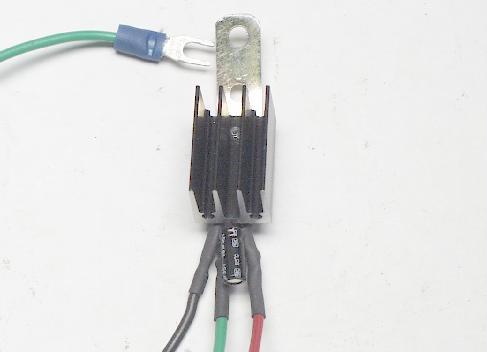
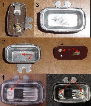
I see this question come up alot so I decided to snap some pics and post them. Here is the procedure to convert the instrument cluster voltage regulator from analog to solid state. The mod gives you a constant 5.0v and a steady readout on your gauges. I will refer to the voltage regulator assembly as VR. Figure 1 shows the VR with the crimped edge bent back to allow the bakelite insulator to be removed. The next step(Figure2) is to grind the spotwelds smooth so the new regulator will sit flush. It is important that it sits flush against the case so that it can transfer heat. On the bottom side of the bakelite insulator you will see two metal strips. These can be removed by bending them back and snapping them off. Be careful not to loosen the lugs that are attatched to the other side.
Figure 4.Now that the case is bare, locate and drill a hole to mount the new VR IC. Remove any burs or shavings from the case. You will be using a standard 7805 +5VDC voltage regulator IC. It is readily available at Radio Shack(cat no. 276-1770a) for about $3. Apply a thin layer of heat sink compound on the back of the IC prior to installation. I use silver based compound but the cheap Radio Shack white silicone compound will work fine. Now you are ready to attatch the IC to the inside of the case. Again, be sure it sits flush. You can use a small machine screw and nut or pop rivit to secure the IC. I use a solid, silver plated brass rivit
.Figure5. Push the middle leg of the IC down so that its touching the case and solder it directly to the case. This is the ground. I also solder the head of the rivit to the head of the IC as an additional ground and to help secure the IC.
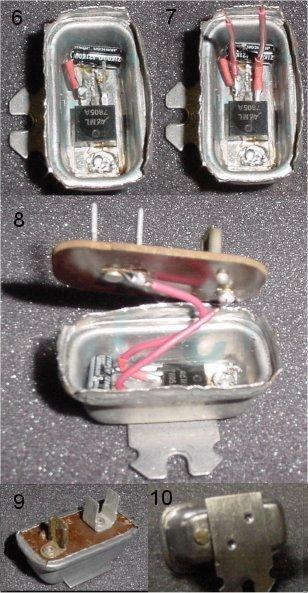
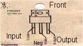
Figure6. Here I have attatched a capacitor to the IC. The capacitor takes the place of the condensor(external).(Radio Shack 10uF cap #272-1025) The stock condenser should not be used with this conversion. To attatch the capacitor, solder the negative lead directly to the ground(middle) leg of the IC. Next solder the positive side of the capacitor to the input leg of the IC. Refer to the diagram below for the orientation of the input/output on the IC. This will also be printed on the back of the package. Protect the output capacitor lead from shorting out on the case by placing a piece of heat shrink tubing on it before soldering.
Figure7. Solder a short piece of wire to both the input and output legs of the IC. These will be soldered to the lugs on the bakelite insulator. Figure8. All connections have been made and the VR is ready to be reassembled. Make sure there are no wires touching the case. Place the bakelite insulator back on the case and crimp the edge back carefully. Figure 9&10. The conversion is complete and ready to be reinstalled to your instrument cluster.
|
 |
I offer the service to those who would like a solid state regulator but do not want to do the conversion themselves. At this time, you will need to supply a regulator core for the conversion. Email me for more details.
Enjoy,
340_6Pak_cuda
I am bench testing one on a set of rallye gauges right now. I have all three gauges hooked to a potentiometer and they are fully loaded. Ambient temperature is 78f and shell temp is 120f. Max temp on the VR is 160f. I will let them go like this for a day or two and monitor the temps.
The push in style ones will surely have to have a heatsink on them. I think A body used them and others also.
Another option on cooling would be to epoxy fill them. It would give more surface area to dissipate heat off the IC.

Tech Index